A 1920s patent for a centrifugal switch us patent 1630394 was granted to royal lee on may 31 1927. The electronic switch interrupts the start circuit current after the motor has accelerated to the cut out speed and reconnects the start circuit whenever the motor speed has decreased to a preselected cut in rpm level.

Wiring Schematic Diagnostics Frigidaire Electric Dryer
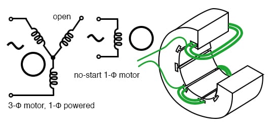
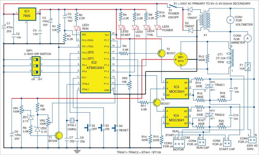
Electronic centrifugal switch circuit diagram. Once the motor comes up to its operating speed the switch. Perhaps the most common use of centrifugal switches is within single phase split phase induction motorshere the switch is used to disconnect the starting winding of the motor once the motor. This switch disconnects the motor start capacitors from the circuit once the motor is up to speed. A non electronic proximity switch would use the same symbol as the lever actuated limit switch. The symbol shown here for the proximity switch is of the electronic variety as indicated by the diamond shaped box surrounding the switch. An electronic switch does not respond to the speed of the motor shaft like a centrifugal switch does but has a timed disconnect.
Centrifugal switch start metropolitan. Current 12 16 25 35 40 50 sinpac switch ordering and. Centrifugal switch motor connection with diagram. A centrifugal switch solves a problem inherent in single phase ac electric motors. It allows the starting windings to be engaged for 74 seconds and then breaks the circuit. A centrifugal switch is an electrical switch that operates using the centrifugal force created from a rotating shaft most commonly that of an electric motorthe switch is designed to activate or de activate as a function of the rotational speed of the shaft.
Centrifugal switch start metropolitan vickers electric motor refurb duration. The centrifugal switch turns on a circuit providing the needed boost to start the motor. Electronic centrifugal switches samusco duration. By themselves they dont develop enough torque to begin turning from a dead stop. Capacitor startcapacitor run motors exhibit current transients and higher voltages across the start switch. It is also possible to buy an electronic switch to replace the centrifugal switch.
It was the basis for the formation of the lee engineering company. Electronics 7 sinpac switch 2 cv series capacitor start only 3 made to order mto 5 ir series capacitor start only 7 vr series capacitor start capacitor run only 8 ivr series capacitor sart capacitor run 1 115 start circuit voltage 2 230 start circuit voltage 0 standard a inductor amps max. Electronic switches cost a bit more than 40. Another form of proximity switch is the optical switch comprised of a light source and photocell. Perhaps the most common use of centrifugal switche is within single phase splitphase induction motors.


