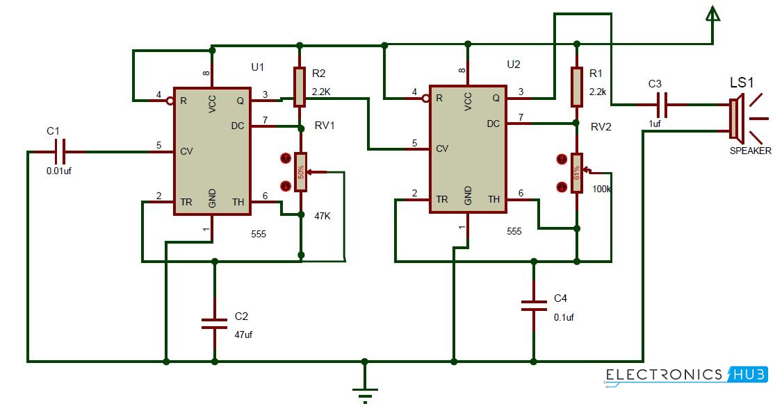
In this ding dong sound generator door bell circuit we have used two separate 555 timer ic to generate ding dong signal. The working principal of the circuit doorbell is simple.

Arduino Based Wireless Doorbell Doorbell Wireless Doorbell
Doorbell circuit diagram pdf. Click on your setup to view the diagrams. A doorbell is a signalling device typically placed near a door to a buildings entrance. The circuit given below is a modified version of the melody generator circuit whose link is given above. The transmission enable pin pin 14 is connected to ground. Wiring diagram for a two chime doorbell. Here we can see that first 555 timer ic is configured in monostable mode means it will go high and low only once if triggered with trigger pin 2.
When a visitor presses a button the bell rings inside the building alerting the occupant to the presence of the visitor. And a 10k r4 resistor 50k pot rv1 between pin 7 and 6. Here we present a simple and cost effective door bell circuit based on ic 8021 2 from formox semiconductors. Circuit diagram and explanation. Connect the input wires on the transformer to the source circuit using the black to black white to white and ground to green method. Other connections are shown in the circuit diagram.
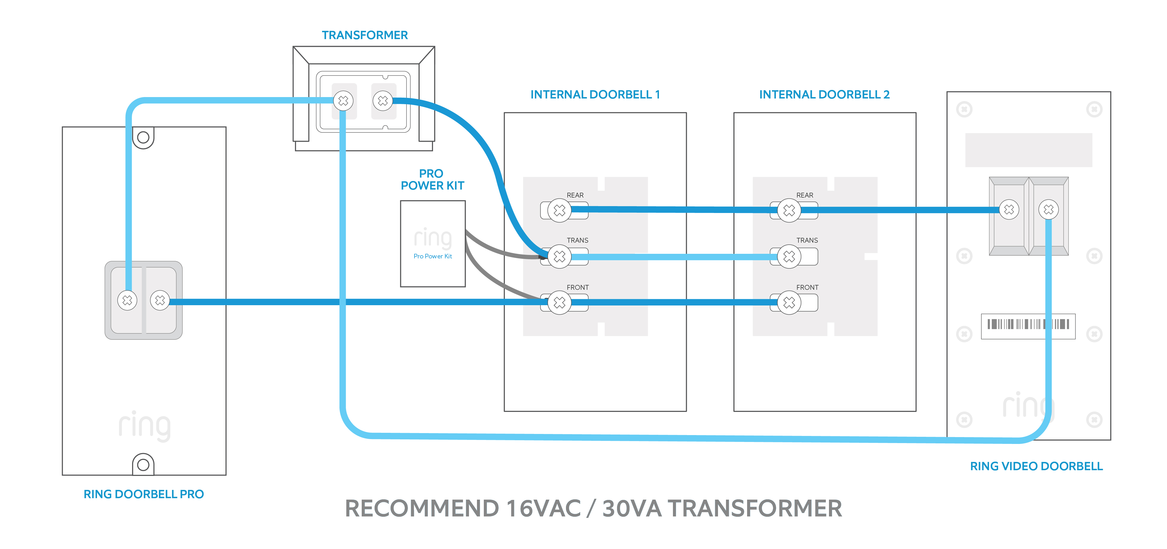
This is a 2 tone doorbell circuit which is an electronic buzzer typesbut them has melodic sound than the general electric bell. Wiring for two doors is the same as for one with the transformer hardwired to the 120 volt source from a house circuit. The main objective of the doorbell circuit is to convert electrical signals input into audio signals output with a single press of a switch. The circuit of the wireless bell shown here is easy to built and using only few easy to find low cost components. There are two switches s2 and s3 for front and rear door respectively. If youre in the process of setting up multiple ring video doorbells internal doorbells and transformers the following wiring diagrams may help.
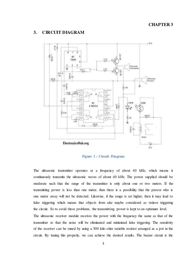
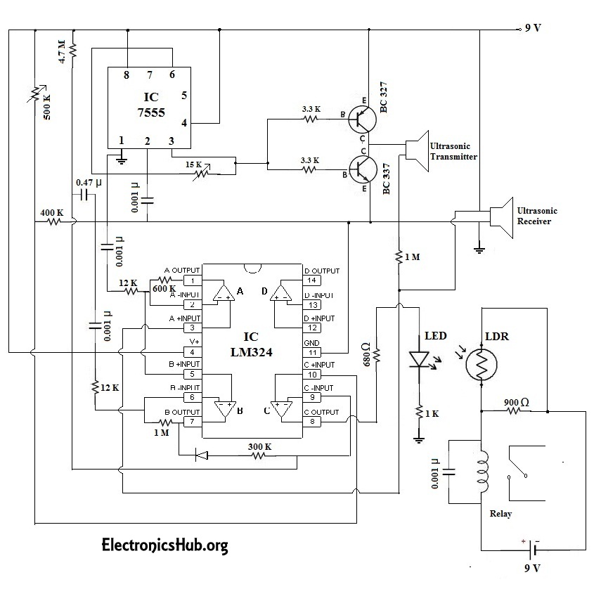
In this case circuit act as a two way doorbell with memory that is the audio alarm indicates whether the visitor is calling from the front door or from back door. But they are circuit that made no who apply them since problems three reasons. Above figure shows the circuit diagram for doorbell. A push button is connected between ad8 pin 10 and ground. A 750 kω is connected between the oscillator pins pins 15 and 16 of the ht 12e. A um66 melody generator is connected at the output of the receiver circuit which will be activated when the receiver circuit receives signals from the transmitter.
Circuit diagram and explanation. Variable resistor rv1 is used to control the ring duration means how long will be the output pin 3 will be high. Melody generator using um 66 door bell circuit using ne555. The s1 is open the circuit act as a two way doorbell. Design of receiver circuit. Which many people have seen the two tone bell sounds from other electronic journals.
In first 555 timer ic we have connected a 1k r1 resistor between vcc pin 7th of 555 timer u1.


.jpg)


