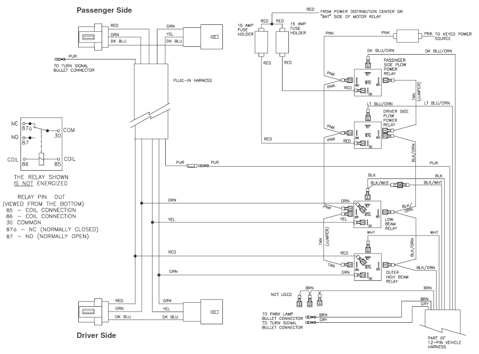
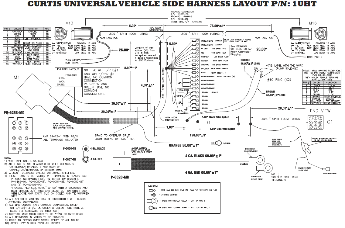
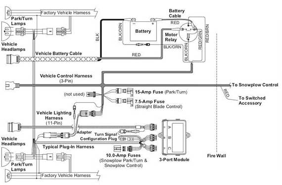
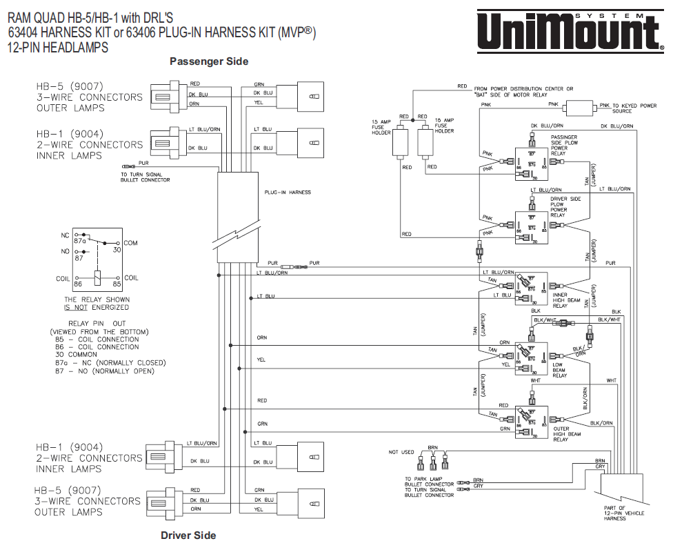
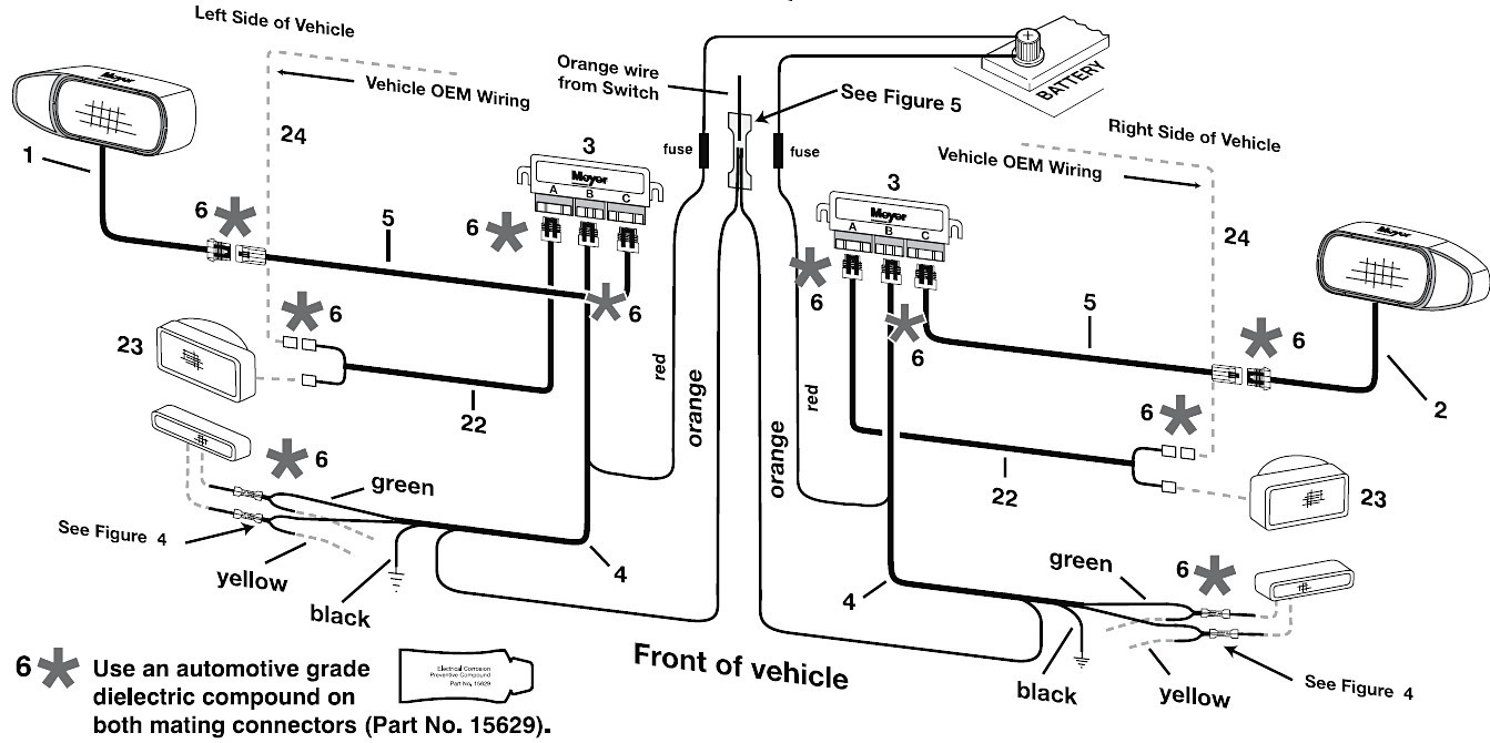
Boss wiring harness. Microsoft word 11 pin manifold wiring diagramsdoc author.
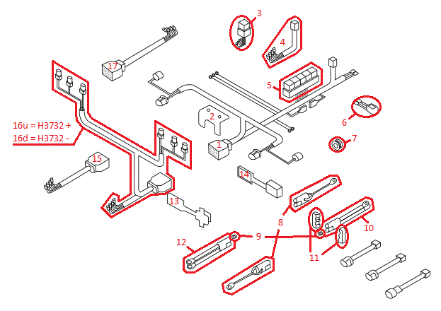
11 Pin Boss Plow Wiring Diagram Wiring Diagrams Dat
Boss plow 11 pin wiring diagram. Wiring diagram smartlight2 wiring schematic smartlight2 control plug pin functions. 8 red yellow plow low beam. Pin wire color function 1 red passenger side out. Rt3 wiring diagram rt3 wiring diagram. 10 pink right turn. 6 red black driver side in.
3 white raise. Wiring schematic wiring schematic g10004. Boss wiring harness. 5 blue driver side out. Shock absorber option kit 10 is standard on all super duty straight blade plows. 10 pink right turn.
It will show you how to use and service the boss familiarize you with all of its parts and give you helpful hints on plowing snow. 9 n a n a. 8272004 95947 pm. Lowest prices for the best snow plow parts from sam. 7 gray black plow high beam. Smarthitch manifold wiring diagrams rt3 power v blade with smarthitch manifold g10003 rt3 straight blade with smarthitch manifold g10042 jumper wire red redblack orange jumper wire black white blue green jumper wire smart hitch selector switch.
Pin wire color function 1 red passenger side out. If you have further questions your local boss plow dealer is the person to talk to. 3 white raise. 8 gray plow low beam. 2 green passenger side in. 7 blue yellow plow high beam.
9 white yellow plow common. Shock mount attachment g10061 11 x 3 hex head cap screw 10c and 58 11 note. 5 blue driver side out. 6 red black driver side in. 4 orange lower. 4 orange lower.
Electrical system wiring schematic truck side electrical system wiring schematic truck side g10272. 11 pin. 2 green passenger side in. To keep your boss snowplow in top condition take a few minutes to study this manual. Microsoft word 13 pin wiring schematicdoc author. Snowplow assembly procedure 5 figure 4.
Electrical system wiring schematic plow side g10271. 13 pin.

