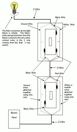
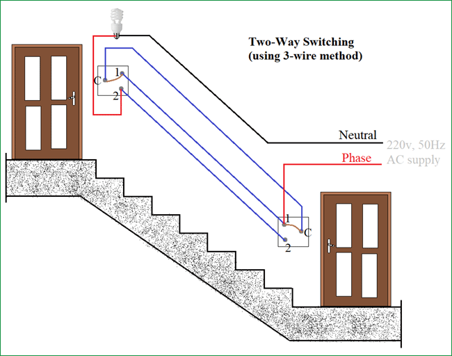
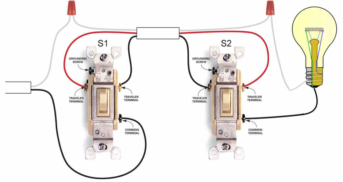
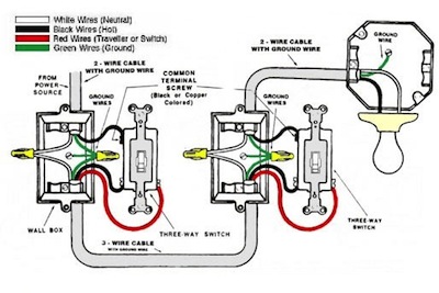
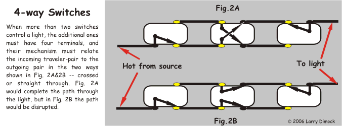
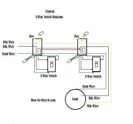
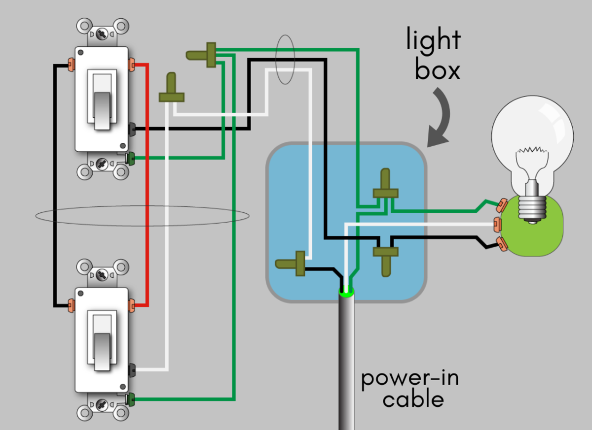
3 way switch wiring diagram. Wiring diagram 3 way switch with light at the end.
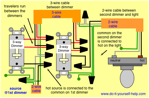
3 Way Switch Wiring Diagrams Do It Yourself Help Com
Basic 3 way switch diagram. Wiring a 3 way light switch. The first step in any electrical project is to make sure there is no power going to the circuit you plan to be working on. Wires consisting of a line a load a neutral a pair of travelers and two 3 way switches. Basic 3 way switch diagram how to wire 3 way light switch step by step. When wiring a 3 way switch circuit we will be using a 3 wire cable known as romex coming from the source such as the breaker box. Each 3 way switch in these examples are controlling the power source to the same load.
If you have any problems with these switches it may be best to call an electrician. 3 way switched outlet wiring. The figure below shows the simplest possible configuration. This might seem intimidating but it does not have to be. Wiring a 3 way light switch is certainly more complicated than that of the more common single pole switch but you can figure it out if you follow our 3 way switch wiring diagram. This wire diagram shows the wiring for source power into the first three way switch then 3 wire cable to the next 3 way light switch and then on to the light or light fixtures.
With these diagrams below it will take the guess work out of wiring. Lets start by looking at how a normal light is wired so that you can understand basic residential wiring for a light switch. With a pair of 3 way switches either can make or break the connection that completes the circuit to the light. The basic 3 way switch wiring diagram this is the most common and the easiest wiring diagram to follow of any of the wiring diagrams for a 3 way switch circuit. In this diagram the black wire is hot that is it carries the 120 volt ac current. In this diagram two 3 way switches control a wall receptacle outlet that may be used to control a lamp from two entrances to a room.
Then a 4 wire cable going between the two 3 way switches and then a 3 wire cable going from the switches to the load. Take a closer look at a 3 way switch wiring diagram. This circuit is wired the same way as the 3 way lights at this link. Three wire cable runs between the switches and the outlet. Pick the diagram that is most like the scenario you are in and see if you can wire your switch. Turn the power off at circuit breaker.
If you are trying to troubleshoot a 3 way switch operation you will need to identify the function of each wire. Be sure to identify the electrical circuit correctly youll be wiring into and turn off the. In this diagram the electrical source is at the first switch and the light is located at the end of the circuit. All three way switch and 2 way switch wiring diagrams have the same basic components. The diagrams below show the conventional wiring for 3 way switches. Three wire cable runs between the switches and 2 wire cable runs to the light.
The white wire is neutral. Unfortunately not all 3 way switches are wired the conventional way. See alternate 3 way switch wiring configuration for another way 3 way switches may be wired. The black and red wires between sw1 and sw2 are connected to the traveler terminals.
