Large electric motors can be protected from overcurrent damage through the use of. These lines far exceed the 120 volts ac standard in most homes.

Contactor Wiring Guide For 3 Phase Motor With Circuit Breaker
3 phase motor contactor connection. Contactor wiring with complete explanation. 240 volts ac and 480 volts ac are commonly used for these large pieces of. Motor starter म contactor holding circuit क कय जररत हत ह electric guru duration. A contactor is a large relay usually used to switch current to an electric motor or another high power load. Many large pieces of equipment are powered directly from high voltage lines. Assortment of 3 phase motor contactor wiring diagram.
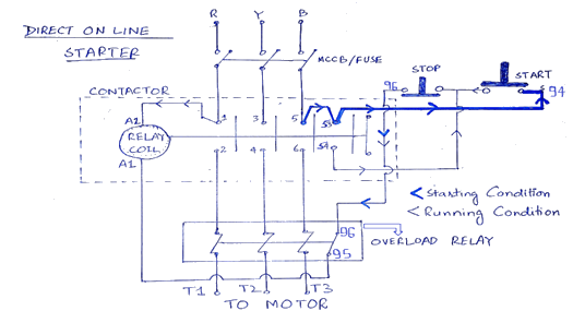
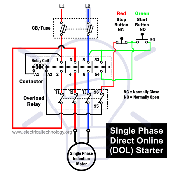
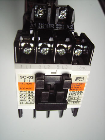
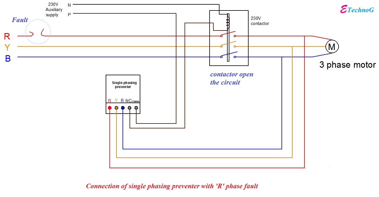
3 phase motor contactor wiring diagram contactor wiring diagram for three phase motor. A three phase contactor is an electronic device used to turn power on or off at a three phase load. It reveals the parts of the circuit as simplified forms as well as the power as well as signal connections in between the tools. How to wire a contactor. Posted january 18 2018 by springercontrols. Contactor wiring guide for 3 phase motor with circuit breaker overload relay nc no switches.
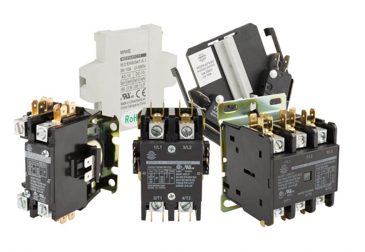
Contactors are typically used on three phase air conditioning motors requiring at least 480 volts to operate. Single phase power is typically reserved for lower power requirements however in some cases powering a small motor with single phase input power is practical. In 3 power system we use some devices between induction motor and supply which are a cb circuit breaker mc magnetic cont actor or motor stater ol overload relay and nc no push button switches for onoff and reset. Wiring a single phase motor through a 3 phase contactor. I shown the 3 pole mccb circuit breaker 2 magnetic contactor normally open normally close push button switch thermal overload relay 3 phase 4 wire system supply 3 phase motor with connection trip indicator light etc. Wiring diagram pics detail.
Ac blower motor wiring diagram furthermore 3 phase star delta motor connection diagram besides dc electrical motor wiring diagram further 813 tube lifier schematic furthermore three phase induction motor rotor and stator. Electric guru 35760 views 1404. A wiring diagram is a simplified conventional pictorial representation of an electric circuit. These devices are used when the voltage requirements of the load exceed the power handling capability of a mechanical relay. In the 3 phase motor forward reverse starter wiring diagram. Home about us news wiring a single phase motor through a 3 phase contactor.


